Caching Topologies: Client, CDN, In-Memory & Distributed Redis Architecture
A resilient caching architecture is not a single Redis cluster, but a multi-tier hierarchy spanning edge, process memory, and distributed stores. This article explores HTTP edge revalidation, in-process L1 memory vs. distributed L2 Redis, RESP3 client-side tracking, and Redis Cluster hash-slot sharding.
Caching & Distributed Concurrency
Caching Topologies: Client, CDN, In-Memory & Distributed Redis Architecture
A cache is not an optimization layer you sprinkle over slow queries — it is a volatile, distributed state machine with independent failure modes and eventual consistency tradeoffs. Every cache hit is a loan against consistency; every cache miss is a potential stampede. The most pervasive broken pattern in backend engineering is treating caching as a monolithic, single-node key-value store slapped between an API service and a PostgreSQL database. Engineers configure a basic Redis instance, wrap database queries in redis.get() and redis.set(), and assume their data access layer is scaled. In reality, a resilient architecture is a coordinated multi-tier hierarchy spanning edge CDNs, in-process memory, and distributed clusters. When you fail to design these tiers explicitly, adding caches does not solve latency — it simply multiplies your stale-read failure domains.
Series positioning: This is Part 1 of the Caching & Distributed Concurrency series. It establishes the multi-tier caching hierarchy, HTTP edge protocols, in-process L1 synchronization, and distributed Redis cluster topologies that underpin the invalidation strategies (Part 2), high-concurrency resilience engines (Part 3), and distributed locks (Part 4) explored in subsequent articles.
1. The Multi-Tier Caching Continuum
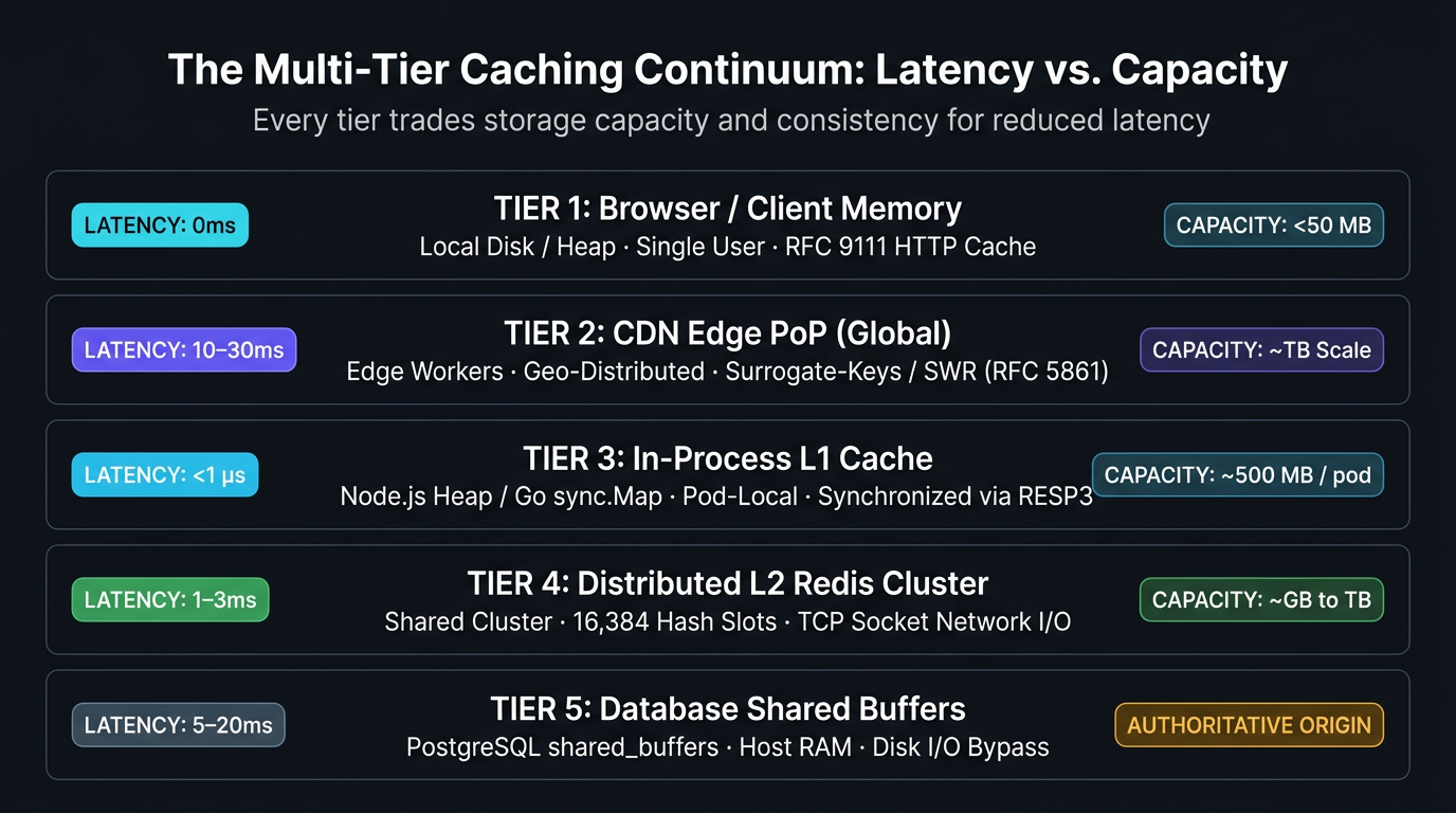
Every millisecond of latency saved is governed by where data lives relative to the execution runtime. Caching is not a binary choice between "in memory" and "on disk" — it is a continuous spectrum spanning physical hardware, network boundaries, and process memory spaces.
| Caching Layer | Typical Latency | Implementation Mechanism & Protocol |
|---|---|---|
| Client / Browser Cache | 0ms |
Local disk / memory heap (RFC 9111 HTTP Cache) |
| CDN Edge PoPs | 10–30ms |
Global edge workers & reverse proxies (RFC 5861 SWR) |
| Reverse Proxy / Gateway | 1–3ms |
Nginx / Envoy micro-cache / shared memory |
| In-Process L1 Memory | <1µs |
Node.js heap / Go sync.Map (RESP3 Client Tracking) |
| Distributed L2 Redis | 1–3ms |
Shared Redis cluster over TCP network socket |
| Database Buffer Pool | 0.1–1ms |
PostgreSQL shared_buffers (host RAM disk I/O bypass) |
1.1 The Latency & Storage Spectrum
Each caching tier operates under distinct physical constraints:
| Tier | Typical Latency | Storage Medium | Scope & Volatility | Primary Invalidation Mechanism |
|---|---|---|---|---|
| Browser / Client | 0ms (memory) / 5ms (disk) |
Client device RAM/Flash | Single user; highly volatile | Cache-Control max-age, ETag revalidation |
| CDN Edge PoP | 10–30ms |
Edge server SSD & RAM | Global geo-distributed; shared | Surrogate-Keys / Cache-Tags, SWR background fetch |
| Reverse Proxy | 1–3ms |
Gateway memory | Regional / VPC ingress | Internal micro-cache TTL (proxy_cache_valid) |
| In-Process L1 | <1µs (nanoseconds) |
Application heap RAM | Pod-local; dies on process restart | TTL, LRU eviction, RESP3 invalidation push |
| Distributed L2 | 1–3ms |
Redis / Valkey RAM | Cluster-wide; shared across all pods | Explicit DEL/UNLINK, CDC event stream, TTL |
| DB Buffer Pool | 0.1–1ms |
Database shared_buffers |
DB node host RAM | LRU clock sweep, table write invalidation |
1.2 The Failure Cascade
When an upper tier suffers a high miss rate or an uncoordinated invalidation event, traffic immediately falls through to lower tiers. Because lower tiers have orders-of-magnitude smaller concurrency tolerances than upper tiers, a 10% drop in CDN cache hit ratio can increase database load by 500%, causing connection pool exhaustion. Designing a multi-tier topology requires setting capacity limits at every boundary.
2. HTTP Caching & Edge Control: RFC 9111, SWR & Surrogate-Keys
The fastest request is the one that never touches your origin infrastructure. HTTP caching at the CDN edge (Cloudflare, Fastly, AWS CloudFront) is your first line of defense, but standard Cache-Control: max-age=300 is fundamentally unsuited for dynamic API payloads where data freshness matters.
2.1 Modern Directives: s-maxage, stale-while-revalidate & immutable
HTTP specifications (RFC 9111 and RFC 5861) allow fine-grained decoupling between browser caches, shared CDN caches, and background revalidation routines.
max-age=0: Instructs browser clients not to serve from local disk without checking the origin/CDN.s-maxage=300: Instructs shared intermediate proxies (CDNs) to consider the asset fresh for 5 minutes.stale-while-revalidate=60(RFC 5861): When the 5-minutes-maxageexpires, the CDN edge serves the stale cached payload immediately to the client within the 60-second window while firing an asynchronous background sub-request to the origin to refresh the cache.stale-if-error=86400: If the origin returns a5xxerror or times out, the CDN serves the stale payload for up to 24 hours rather than returning an error page to the user.
2.2 Instant Edge Purging with Surrogate-Keys
A long CDN TTL gives near-100% cache hit ratios, but updating state (e.g., price drop, product stock change) renders the edge stale. Polling or short TTLs waste origin CPU. The production pattern is Surrogate-Key (Cache-Tag) indexing:
- When rendering
GET /api/v1/products/9871, the origin tags the response withSurrogate-Key: product_9871 tenant_42. - The CDN indexes the cached edge object under both tags.
- When an administrator updates Product 9871, the backend issues an asynchronous API call to the CDN's Purge API:
BASH
2.3 The Vary Header Trap
A major source of CDN cache misses and memory bloat is improper use of the Vary header. When you specify Vary: User-Agent or Vary: Cookie, the CDN generates a completely distinct cache entry for every unique browser version or session token.
Never set Vary: Cookie or Vary: Authorization on cacheable public endpoints. Doing so fragments the CDN cache ratio to near 0%. If an endpoint returns personalized data alongside public data, strip authentication headers at the edge or isolate private fields to a separate un-cached sub-request.
3. In-Process L1 vs. Distributed L2: The Pod Split-Brain Problem
In high-throughput microservices, querying Redis over a TCP socket costs 1–3ms of network latency plus serialization overhead (JSON.parse). In-process memory (heap) resolves in <1µs. However, deploying in-process caches across horizontally scaled server pods introduces a critical distributed systems hazard: multi-pod cache split-brain.
3.1 Redis RESP3 Client-Side Tracking
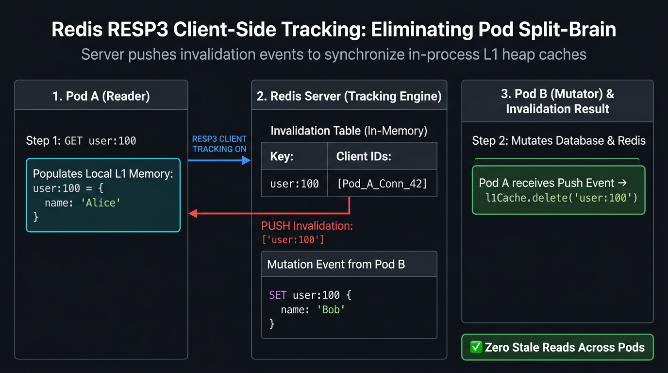
To eliminate pod split-brain without discarding the microsecond performance of L1 caches, Redis 6 introduced and Redis 7/8 refined Server-Assisted Client-Side Caching via the RESP3 protocol.
With RESP3 tracking:
- When Pod 1 reads
user:100from Redis, Redis records in its internal Invalidation Table that connection IDXholdsuser:100. - Pod 1 stores
user:100in its local in-memory L1 cache. - When Pod 2 mutates
user:100viaSET user:100 ..., Redis checks its tracking table and pushes an asynchronous invalidation message (invalidate ["user:100"]) over the TCP connection to Pod 1. - Pod 1 receives the message and immediately deletes
user:100from its local heap memory.
3.2 Standard Tracking vs. Broadcast (BCAST) Mode
Redis supports two tracking implementations:
| Mode | Tracking Mechanism | Server Memory Overhead | Client Message Traffic | Best Use Case |
|---|---|---|---|---|
| Standard Mode | Redis tracks individual key read per client connection ID | Scales linearly with cached keys ($O(N)$ memory on Redis) | Low (only receives invalidations for exact keys read) | Predictable, bounded key sets with high read/write ratio |
Broadcast Mode (BCAST) |
Redis matches keys against prefix trees (e.g. users:) |
Zero server tracking memory ($O(1)$ memory on Redis) | High (clients receive invalidations for all mutations under prefix) | Massive key spaces (millions of keys) or bursty multi-pod clusters |
4. Distributed Cache Clustering & Topology Engineering
When working set sizes exceed the RAM capacity of a single Redis node, or when write throughput saturates single-threaded event loop capacity, the caching layer must scale horizontally across a Redis Cluster.
4.1 Hash Slots & Key Distribution
Redis Cluster does not use consistent hashing rings by default; instead, it partitions the entire dataset across fixed 16,384 Hash Slots. Every key is assigned to a slot using the CRC16 checksum:
$$\text{slot} = \text{CRC16}(\text{key}) \pmod{16384}$$
Each master node in the cluster is responsible for a contiguous subset of the 16,384 slots (e.g., Node A owns 0–5460, Node B owns 5461–10922, Node C owns 10923–16383).
| Cluster Master Node | Hash Slots Assigned | Replicated By |
|---|---|---|
| Node A (Master) | 0 – 5460 |
Replica A1 |
| Node B (Master) | 5461 – 10922 |
Replica B1 |
| Node C (Master) | 10923 – 16383 |
Replica C1 |
4.2 Multi-Key Operations & Hash Tags
In a Redis Cluster, multi-key commands (MGET, MSET, transactions MULTI/EXEC, and Lua scripts) are strictly prohibited if the participating keys map to different hash slots. Attempting to run MGET user:100:profile user:100:orders triggers a CROSSSLOT Keys in request don't hash to the same slot exception.
To force related keys onto the exact same hash slot and cluster node, use Hash Tags ({...}):
4.3 The Hot Key Skew Problem & Two-Tier Key Salting
A critical vulnerability in clustered caching is Key Skew. If your application has a viral product or breaking news item, hashing that key routes 100% of read traffic to a single master node. The other 99 nodes in your cluster sit idle while Node C's network bandwidth saturates and its event loop drops connections.
Summary
| Architectural Concern | Production Rule |
|---|---|
| Multi-Tier Continuum | Caching is a continuous latency hierarchy; never rely on a single Redis tier when edge CDNs and in-process L1 memory can short-circuit 90% of network hops. |
| Edge Revalidation | Combine s-maxage with stale-while-revalidate (RFC 5861) to return instant cached responses while asynchronously refreshing stale assets at edge PoPs. |
| Edge Invalidation | Use Surrogate-Keys / Cache-Tags to execute sub-150ms global cache purges across thousands of CDN PoPs without dropping hit ratios. |
| Pod Split-Brain | In-process L1 caching causes multi-pod state divergence; synchronize local heap caches using Redis RESP3 server-assisted tracking invalidation streams. |
| Cluster Sharding | Multi-key Redis commands fail across cluster nodes unless keys share Hash Tags ({tenant_id}:data) to guarantee co-location on the same hash slot. |
| Hot Key Saturation | Ultra-hot keys bottleneck individual cluster nodes; apply randomized key salting (key:salt_N) across N slots alongside L1 caching. |
What's Next
Now that we have established the multi-tier caching hierarchy and cluster topologies, Part 2: Cache Write Strategies & Invalidation Architectures tackles the hardest problem in distributed state: solving the dual-write race condition, managing Write-Back crash durability, and implementing Change Data Capture (CDC) pipelines.
This article was developed with AI-assisted deep search, specification cross-referencing, and technical research synthesis.